+/- 15 Volt Power Supply In various module construction articles, I state that you should connect the module in question to a power supply set aside for more "noisy" modules. While this is not essential, it is the easiest way of keeping noise generated by digital modules from the more sensitive analog modules. This project is ideal for this. Different voltage regulators can also be used to give +/- 5 volts, +/- 9 volts, +/- 12 volts or +/- 18 volts, or any other voltage for which 78XX and 79XX regulators are available, as long as the appropriate AC voltage is fed to the unit. Note: this project may require wiring a transformer to the A.C mains. This is best left to people who are qualified to do so. Where possible, use a plug-pack, wall-wart or line-lump, or other product where the mains wiring has already been done. How to use this module: This module is designed to connect to various modules using a distribution board such as the Oakley Modular Systems power distribution board or those sold by Synthesis Technology and Blacet Research Music Products. Most of my modules conform to the power supply standard adopted by these manufacturers. A little on how it works:
The schematic of the power supply. The circuit is as basic as it gets. The incoming AC power is rectified, then filtered. The filtered DC is regulated by the positive and negative voltage regulators. The regulator minimum load requirements are met by placing a LED and its associated resistor between each output and the 0 volt (ground) line. Capacitors are placed close to the input and output pins of the regulators to improve stability and transient response . Two additional diodes per regulator protect the regulators should the outputs be shorted together, or should a voltage be fed into the output of the power supply. It is very much a standard configuration, detailed in many data books, and no doubt available in as various kits from many places. My first kit of this was produced back in the early eighties, and the circuit hasn't changed, though the PCB layout is new. When fed from a 30 volt center tapped transformer (15v-0v-15v) you should be able to pull around 200ma from the PSU without problems. There will be minimal heat generated by the regulators because they will be running close to their minimum voltage drop, though you do risk ripple getting through to the output as the load increases. When fed from a 36 volt center tapped transformer (18v-0v-18v) you should be able to pull around 600ma from the PSU without problems. There will be a fair amount of heat generated by the regulators and diodes, so make sure there is adequate airflow around the board. 600ma is close to the maximum D.C. current you can draw from this PSU when powered from a 1 amp transformer. You may also wish to use 3300 mfd 25 volt capacitors instead of the specified 2200 mfd. Drawing more than 600ma, while possible with a larger transformer, is not recommended, as there is inadequate heatsinking on a number of components, and the electrolytic capacitors are much too close to the heatsinks. The prototype was tested running at over 800ma output using 3300 mfd filter capacitors and a 36 volt transformer. Another factor limiting the maximum current that can be drawn from the unit is the size of the heatsink. With 600ma being drawn, each regulator can easily be dissipating 6 watts, and will require a heatsink with a rating of 12°C/W or better to operate in an ambient of 25°C. As heat in an enclosed space may well be greater than this, I'd recommend going for the best heatsink of the correct profile you can get. Hobby shops in Australia have them available at 8.5°C/W (50 mm) and 11°C/W (40 mm), depending on the shop, though I have used 63 mm heatsinks I salvaged from old switch-mode power supplies. The profile used is simply listed as PCB mount TOP-3 in the local catalogs.
Construction
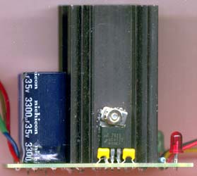
The overlay of the Power supply. Before you start assembly, check the board for etching faults. Look for any shorts between tracks, or open circuits due to over etching. Take this opportunity to sand the edges of the board if needed, removing any splinters or rough edges. When you are happy with the printed circuit board, construction can proceed as normal, starting with the diodes and resistors first, followed by the taller components. Take particular care with the orientation of the polarized components such as the diodes, electrolytics, LEDs and regulators. The easiest way to install the regulators is to mount them on the heatsinks before installing them and the heatsinks on the PCB. The heatsink mounting holes may need enlarging to accommodate the pins of your selected heatsink. The heatsink I have used is of a very common extruded profile and is available in differing lengths. See above for more details. Notes:
Parts list This is a guide only. Parts needed will vary with individual constructor's needs. If anyone is interested in buying one of these boards, please check the PCBs for Sale page to see if I have any in stock. Can't find the parts? See the parts FAQ to see if I've already answered the question.
Disclaimer
A note to readers:
All electronic projects and designs presented on this web site, or associated web sites should be considered dangerous if not lethal if not used safely. When working on projects based on these designs, use extreme care to ensure that you do not come into contact with mains AC voltages or high voltage DC.
If you are not confident about working with mains voltages, or high voltages, or you are not legally allowed to work with mains voltages, or high voltages, you are advised not to attempt work on them. The author, host, and all people associated with these web pages disclaim any liability for damages should anyone be killed or injured while working on these projects, or projects based on these designs, or any other project or design presented on these web pages and any associated web pages.
The author, host, and all people associated with these web pages also disclaim any liability for projects, or projects based on these designs, or any other project or design presented on these web pages and any associated web pages when used in such a way as to infringe relevant government regulations and by-laws.
Article, art & design copyright 2001 by Ken Stone
| ||||||||||||||||||||||||||||||||